Advantages of Braiding Technology
Tadashi UOZUMI
Braider Section, Murata Machinery, Ltd.
136, Takeda-Mukaishiro-cho, Fushimi-ku, Kyoto 612-8418, Japan
ADVANTAGES OF BRAIDING TECHNOLOGY
Braiding technology has potential for reducing costs. Braiding technology has been improved to fabricate near-net-shaped fiber preforms of complex shaped composite materials(1). We have also improved automation technology using the braiding technology. The cost of labor is the biggest individual cost. Automation technology is the most efficient way to reduce the production costs. We are working not only to improve automation of individual machines such as a braiding machine, but also to improve the automation of complete production systems of which a braiding machine is one component(2). In this paper, the following two items are forced on as the advantages of braiding technology,- Automation technology
- Impact properties of braided composite pipes
One of the automatic braiding systems is shown in Fig.1. The system is so efficient to reduce the production cost that it has been used for producing golf shafts as shown in Fig.2 (3). In this system, braided preforms of composite tube are fabricated automatically and continuously. The system consists of a mandrel stock unit, a mandrel supply unit, braider units, a preform pick-up unit and a preform stock unit. A mandrel is supplied to the front of the braider units from the mandrel stock unit. Braided preform is fabricated on the mandrel during the mandrel goes through the multiple braider units. Braiding yarns are cut at the end of the mandrel after braiding. The preform is stocked in the preform stock unit. These processes are carried forward automatically and continuously. Since the system has the multiple braider units, several layers or plies of fabric can be braided over each other to produce the required thickness in one process. Furthermore the fiber orientation angles are varied along the longitudinal direction on each layer, since each braider units are controlled individually by using program.
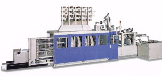
Fig.1 An automatic braiding system.
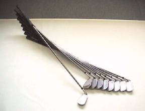
Fig.2 Golf shafts made by automatic braiding system
Braiding technology has potential for optimal design of braided composite. Braiding technologies can be applied to design parameters of varied configuration, various materials and various molding methods. Braided composite properties were optimized through the selection of the design parameters. Braiding technology is useful to make near-net-shaped preforms such as bending type, branching off type and variable diameter type. Carbon fibers, Sic fibers and tow prepregs can be used to meet the design requirements. Plural yarn materials and/or yarn sizes can be selected to make fiber hybrid structures. By preform stitching, braided fabric is stitched in order to increase interlamina strength and to keep the configuration.
IMPACT PROPERTIES OF BRAIDED COMPOSITE PIPES
The braided composite pipes were prepared as shown in Table 1. Table 1 indicates braiding patterns, percentage of 0°yarns, dimensions and bending modulus of each types. The impact properties of braided composite pipes were evaluated and compared with various braiding pattern, materials of fiber and resin. The influence of the fiber orientation angle (braiding angle) on the impact properties were investigated among the specimen types, N60, N45 and N30. The influence of the location of the layer having 0°yarns among the specimen types, N45, N45A and N45B. The influence of fiber hybrid structure and resin hybrid structure among the specimen types, N30, N30V and F30A. The nominal dimensions of the all specimens were 480mm in length, 21mm in inner diameter and 24-24.6 mm in outer diameter.
Carbon fiber and PAR fiber were adopted as reinforcements, and Epoxy and flexible epoxy resin were adopted as matrix resin. In Type N30V, PAR fibers were substituted for half number of 30°carbon fibers to obtain the fiber hybrid structure in the second, third, forth and fifth layers. In the Type F30A, the flexible epoxy resin was used, which was got through all of the 0°fibers to obtain the resin hybrid structure.
The impact properties were evaluated by using the method of three-point-bending test. The bending impact tests were performed at test speed of 5 m/sec. And with a support span of 200 mm. The shape of the loading nose and supports were 11R. The absorbed impact energies were calculated from load-deflection curves in the tests.
Table1 Specimen specifications.
Fig.3 Experimental results of Type N60, N45 andN30.
Fiber Orientation Angle (Braiding Angle)
Fig.3 shows the absorbed impact energies of Type N60, N45 and N30. Type N30 indicated the highest energy. The absorbed impact energy increased with the decrease of the braiding angle. From these results, it is concluded that lower braiding angle causes the absorbed impact energy to improve as well as bending modulus.
Fig.4 Experimental results of Type N45, N45A and N45B.
Location of layer having 0° Yarns
Fig.4 shows the absorbed impact energies of Type N45, N45A and N45B. Type N45A indicated the highest energy, while it indicated the lowest bending modulus. The results suggest that the location of the 0°yarn layer has an effect on the absorbed impact energy. In the Type N45A, the layers having 0°yarns were covered with non-0°-yarn-layers. The layers having 0°yarns indicate higher strength and brittle behavior, and the non-0°-yarn-layers indicate lower strength and tough behavior. It is concluded that the layers having 0°yarns bear the load mainly and the non-0°-yarn-layers constrict the brittle behavior of the layers having 0°yarns. The arrangement of braid layers, that high strength and brittle layers are covered with tough layers, causes the absorbed impact energy to improve.
Fiber / Resin Hybrid Structure
 Fig.5 Experimental results of Type N30, N30V and F30A.
Fig.5 shows the absorbed impact energies of Type N30, N30V and F30A. Both of the Type N30V and F30A indicated the higher energies than Type N30. The results suggest that the fiber hybrid structure and the resin hybrid structure have an effect on the absorbed impact energy. It is concluded that the hybrid structures with high-performance fiber and resin causes the absorbed impact energy to improve.
SUMMERY
In summery, the following conclusions have been made concerning the advantages of the braiding technology described in this paper.
- Braiding technology enables near-net-shaped fiber preform to fabricate automatically.
- Braiding technology enables automatic production system causing the cost to reduce.
- Braiding technology enables improvement of the impact properties by arranging the braid layers in which braiding patterns are arranged to optimize.
- Braiding technology enables the fiber and resin hybrid structure to construct which cause to improve the impact properties
REFERENCES
(1) Z. Maekawa, H. Hamada, A. Yokoyama, A. Fujita, H.Uchida, T. Uozumi and M. Hayashi, Japan International SAMPE Technical Seminar '94 Kyoto, pp. 169 (1994).
(2) Y. Hisa, T. Uozumi, A. Fujita, H. Hamada, A. Nakai and A. Yokoyama, 27th International SAMPE Technical Conference, pp. 371, (1995).
(3) T. Uozumi and M. Hirukawa, 6th Japan International SAMPE Symposium, pp. 497 (1999).